As per tender specifications a direct replacement of existing UF system is focused. The existing plant equipment as I-JF building, civil works, pumps, pipes and instrumentation need to be used. The new ceramic
membrane system needs to be finally connected to existing PLC and
SCADA system with required modification.
• Implementation of CFM Systems into existing UF trains.
• Implementation of sludge slope inside filtration tank.
• Implementation sprinkler system.
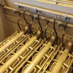
• Installation of CFM Systems Filtration Racks.
• Filtration equipment.
• Central backwash unit.
• Chemical circulation unit.
• Sprinkler unit.
• Blower unit.
• Connection with existing PLC and SCADA.
Introduction
Ceramic System Filtration process has major differences to existing polymer Membrane
process
• Filtration time existing 45-20 min
• Filtration time new Ceramic Filtration 12 hrs
It results in that filtered Iron & Manganese will highly concentrated inside filtration tank
(about 50 times higher to existing polymer system ).
The reachable product (permeate) quality essentially depends on the operation of the
pre-treatment. In general, the CFM Systems pre-filtration step can remove all suspended
solids. It is therewith essentially required to oxidize all Fe and Mn compounds for a
maximized removal and minimized turbidity and SDI levels. Due to the fact that the
structure of the membrane is not effected by using chemicals the permeate quality will
be not changed after a chemical cleaning. The permeate quality is stable and in the
same level before and after each cleaning mode and a long-term operation
guaranteed
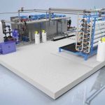
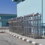
Gallery
Key Benefits
• Less filter area needed due to high flux operation — high CAPEX savings
• Suitable for seawater and other challenging applications without any risks of corrosion problems
• Most compact design — towers can be installed in close distance to each other as no hoses are needed
• Cake layer can be used as additional filter bed for enhanced removal of very small particles and
colloidal fractions
• Sorption processes inside the cake layer enable the selective removal of dissolved contents, like
radium, uranium, arsenic or organics
• Formed cake layer can function as protective coating to minimize biofouling or scaling
• Improvement of filtered water quality can reduce design and process efforts of subsequent treatment
steps Ceramic membranes with very high hydrophilicities — superior for removal of hydrophobic water
contents, like oil
• High flux operation of ceramic flat sheet membrane at very low pressure leads to low power
consumption
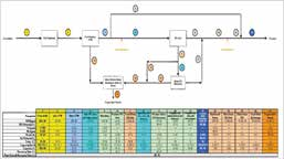
Process Description
• CFM Systems is a submerged filtration solution. The filter active layer is on the outside of themembrane. During the filtration mode feed water will pass the membrane from out-to-in. All suspended solids will form a cake layer on the membrane surface.
• The permeate is collected inside the module and is transferred to the filtration pump which generates a negative-sucking pressure.
• During backwash the flow stream is in the reverse direction. A backwash pump generates a high pressure. Permeate passes the membrane from in-to- out. During this mode the formed cake layer will be removed.
• After re-filling of the filtration with permeate backwash pump and sprinkler pump are stopped and the second aeration starts.
• Process and function of the second aeration are similar to the first aeration.
• Main target is to equalize the sludge inside the tank and therewith to prepare the next drain process.
• In parallel, membranes, modules and permeate piping system will be degassed.
• The degassing valve is opened until the tank is refilled.
• The filtration process can be re-started immediately after the re-filling is finished.